Unexpected stops on a packaging line consume production time, but replacing healthy parts on the calendar also consumes maintenance time. For preventive vs predictive maintenance, keep required scheduled tasks and add condition-based action where a developing failure produces a useful, interpretable warning.
Preventive maintenance follows a calendar or usage schedule; predictive maintenance uses evidence of changing condition to plan intervention. On a packaging line, choose the trigger for each failure mode rather than assigning one strategy to every machine. A conveyor bearing may justify a repeatable vibration route, while a cleaning or inspection task remains scheduled under the applicable manual. The decision needs a measurement method, a defensible alarm criterion, an accountable response and a compatible spare. Collecting sensor data alone does not complete that maintenance process.
Compare the work trigger by failure mode
Use scheduled PM for tasks whose timing is established by the applicable maintenance instructions; use condition evidence to investigate developing faults and plan justified work. The two approaches can serve the same asset.
The public ISO 17359:2018 preview describes a general framework for establishing machine condition-monitoring programmes. Its scope does not establish a universal packaging-line alarm. Clauses 4 and 7 connect monitoring to failure modes; clause 7.4 identifies alternative maintenance strategies when a failure has no measurable symptom.
The table below is an editorial selection aid. Populate its actual tasks and intervals from the installed equipment’s instructions.
| Approach | Trigger and record | Dominant Failure Mode & Prevention | Decision boundary |
|---|---|---|---|
| Calendar or usage-based PM | Due date, operating hours or cycle count specified for the task | Contamination or progressive wear at the relevant contact surface: retain the approved cleaning, inspection or replacement task | A completed scheduled task does not prove that an unrelated developing fault is absent |
| Condition-based action | Repeatable observation crosses an applicable criterion or shows a significant trend | Developing bearing or drive deterioration: investigate the indicated component and confirm the mechanism before selecting corrective work | An abnormal reading is a reason for diagnosis; it is not an exact remaining-life prediction |
| Combined programme | Scheduled task record plus condition findings linked to the same asset | A scheduled task misses an emerging problem, or a sensor misses an unmonitored failure mode: keep both records connected | Removing PM requires a justified change to the applicable maintenance plan |
Start with a component whose failure affects the finished-pack boundary and whose condition can be measured consistently. Record why it is critical: an upstream feeder stop, for example, has different production consequences from a redundant auxiliary unit. Avoid selecting a sensor before naming the failure it is intended to reveal.
Use a bearing limit only within its measurement scope
Apply the limit for the instrument, bearing and operating conditions being assessed. Temperature, overall vibration velocity and enveloped acceleration are different measurements with different interpretation rules.
SKF’s training transcript, pages 3 and 6, distinguishes vibration velocity, bearing-related enveloped acceleration and housing temperature. It describes temperature assessment through historical comparison or similar machines under similar conditions, and calls for an action plan when condition changes. A housing temperature observation should therefore retain its location and operating context; a sealing station’s heat exposure must not become a bearing-failure diagnosis by itself.
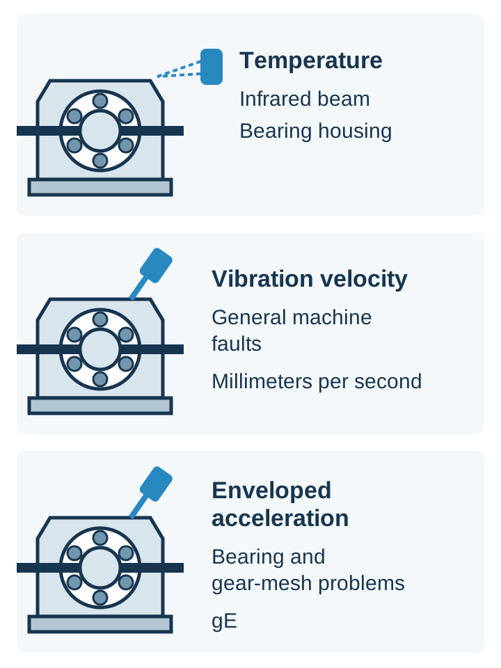
Threshold rule: the SKF CMAS100-SL manual, printed pages 14 and 23, assigns CL3 to bearing bores 20–150 mm at 1,800–3,600 rpm. Its chart lists 4–10 gE as Alert and over 10 gE as Danger. A comparable reading above 4 and below 10 gE within that class warrants condition investigation under the site’s approved response.
These are enveloped-acceleration levels using SKF Band 3, not mm/s velocity limits. Another sensor, analysis band or application needs its own criterion. Confirm applicability before transferring a number to a monitoring plan. An alarm category does not prescribe a repair or restart sequence.
Keep speed, load, product format, measurement point and sensor mounting with each reading. Have the responsible specialist assess a significant change even when a displayed class alarm is absent. Where the installed component’s applicable limit is unknown, obtain it before treating a generic threshold as an operating decision.
Compare recoverable downtime with monitoring overhead
Judge a proposed monitoring task over a matching production period and line boundary. Separate line-stop minutes from technician labor: work done while another machine runs is not automatically recovered production time.
Use this planning equation:
Net line minutes recovered = unplanned line-stop minutes avoided − added planned line-stop minutes − added line-stop minutes for monitoring and investigation.
Hypothetical worked example: assume 240 minutes of breakdown stoppage are avoided over a defined review period, while planned interventions add 90 minutes and monitoring-related stops add 30 minutes. Then 240 − 90 − 30 = 120 net line minutes recovered. These assumed inputs illustrate the calculation; they are not a measured result or a promised saving. For a proposal, test how the result changes when fewer breakdown minutes are avoided, then compare actual records after implementation.
Keep monitoring and analysis labor in a separate cost record, including work that does not stop the line. Also record parts replaced without a confirmed fault, startup scrap and quality-release time. A positive minutes calculation alone does not establish financial payback.
Check whether the spare can arrive before the work is due
Order-after-alert is useful only when the warning allows enough time to obtain and install the correct part. A delivery estimate cannot compensate for an unknown warning interval.
Use the planning condition usable warning time > procurement lead time + work-planning time + safe replacement time, with every term on the same elapsed-time basis. Account for overlapping activities explicitly rather than adding the same hours twice. This is a planning inequality, not a bearing alarm rule. If a credible warning interval cannot be established, retain the contingency appropriate to the asset’s criticality.
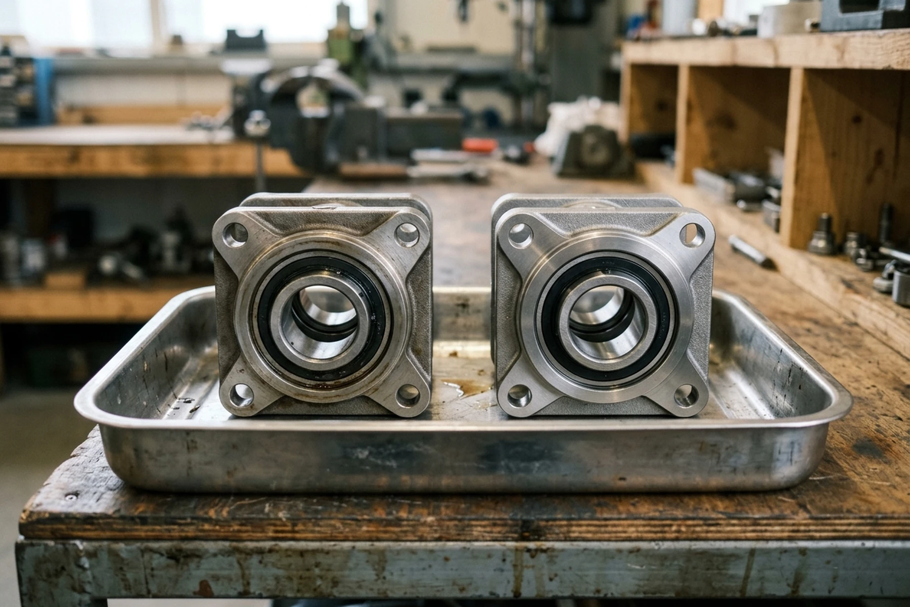
For each critical spare, document the installed part number and revision, compatibility checks, stock condition, confirmed replenishment lead time and responsible owner. Review actual consumption and replenishment together. A lower shelf count is not an improvement if the next failure leaves the line waiting for an incompatible or unavailable component.
Put hidden costs into the maintenance handoff
Make the finding, action and closure evidence traceable before judging the programme. A dashboard alert that no one owns can leave the original downtime risk unresolved.
Use the live packaging-machine maintenance checklist to carry the hidden-cost record across shifts: diagnostic labor, parts used, additional stoppage, discarded packaging and any pending release check. Keep the signal and the confirmed cause separate so that repeated false alarms do not become repeated unnecessary replacements.
Review the programme by component and failure mode. Ask whether the warning was actionable, whether the spare was ready and whether the required verification closed the finding. Return to the packaging machinery guide when the evidence instead points to an equipment or process-boundary decision.
Methods and sources
This comparison applies the public ISO 17359:2018 programme scope, a specific SKF instrument manual and SKF’s measurement training to an editorial maintenance decision record. The older CMAS100-SL manual supplies only the explicitly scoped instrument example; it does not establish a current universal vibration standard. Installed-machine procedures determine actual tasks and responses. The downtime example uses hypothetical assumptions. Updated October 2026.